BIM Day Out – Revit Formulas

Xrev is currenty attending BIM Day Out in Perth, Australia.  We have 2 speaking spots.  A lab on Revit Formulas and a discussion panel on Revit Manufacturer Content.  The first, from the feedback seemed to very successful.  I was a little concerned considering the complexity of the subject matter and the fact it had to be crammed into less than an hour.

For this session, essentially I had setup a single family containing a number of issues you may face with content creation and how to go about using formulas to make a user friendly solution.  Below is the formulas we generated, for those that have the datasets and were unable to keep up or forgot to save…

  1. Stopping an array breaking
    1. if(Task 1 Length / Task 1 Spacing < 2, 2, Task 1 Length / Task 1 Spacing)
  2. Control the number of  connectors
    1. if(Task 2 Connector,3,2)
  3. Control elements based on Family Type selections
    1. if(Task 3 Type = Task 3 Size 1, “1”, if(Task 3 Type = Task 3 Size 2, “2”, “3”))
  4. Using Trigonometry
    1. Task 4 Offset X * tan(Task 4 Angle)
  5. Visibility that is mutually exclusive
    1. Task 5 Value = 1, Task 5 Value = 2, Task 5 Value = 3
  6. Formulas to display error messages
    1. if(and(Task 6 Length > 1000 mm, Task 6 Error), “Too big”, if(and(Task 6 Length < 500 mm, Task 6 Error), “Too Small”, “”))
    2. or(Task 6 Length > 1000 mm, Task 6 Length < 500 mm)
  7. Controlling a Void cut/uncut
    1. if(Task 7 Cut, 0 mm, 220 mm)

For those with the datasets these will make a lot more sense.

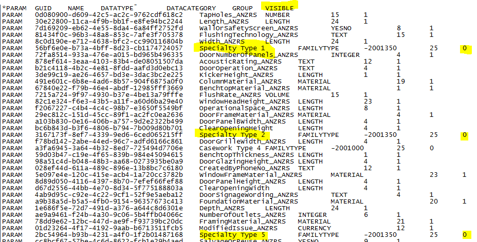
There was also a little trick that I wanted to get to but ran out of time.   It is possible to hide shared parameters from end users by editing the share parameters file.


Hidden Parameters in a shared parameter file

By changing the last integer to 0, you are effectively hiding the parameter from the end user…

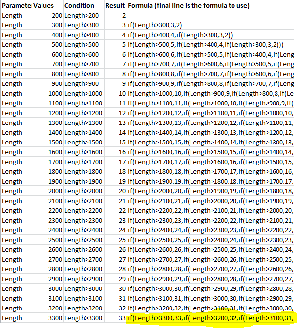
Finally, if you need to write lots of nested if statements it can be somewhat tedious.  I have generated an excel file that allows you to specify the values and the conditions and then there is a formula in the cell that can be “filled down” to write the Revit formula for you.  Then all you need to do is copy the bottom formula into your family and your done…  No need to worry about missing a bracket or syntax errors…

Excel Script

Download the Excel file here

Let me know if you find this useful!

Posted in Promotion | Tagged , | Comments Off on BIM Day Out – Revit Formulas

Xrev Transmit – Matrix Transmittals

At the recent Revit Technology Conference in Auckland we were able to demonstrate our new “Matrix Transmittal” functionality for Xrev Transmit.  By Matrix Transmittal I mean a transmittal that shows all previous issues.

For a long time this has been “the” most requested feature for Xrev Transmit and we have almost completed it!  Expect to see if very soon.

The transmittal is fully customisable, their is a very simple wizard style interface to generate the transmittal and it is linked to your actual Revit revisions so you know its going to be accurate.

Of course we will still support “per issue” transmittals, for those not wanting to display the transmittal history!

Stay tuned…

Posted in Beta Testing, New Features | Tagged , | Comments Off on Xrev Transmit – Matrix Transmittals

Latest Family Creations

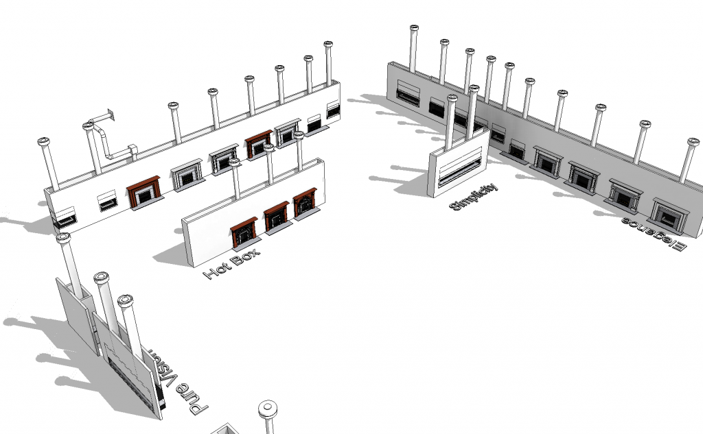
I’ve been busy lately working on some space heaters/fire places for a manufacturer.

Xrev Family Creation - Fireplaces

These family stretch the capabilities of Revit Family Creation whilst still keeping them user friendly.

The user can select what type of Flue they’d like (based upon whats supported for the particular model) EG: Natural, Balanced, Existing Fireplace or Powered.  They can specify how many bends they’d like and the family paramagically adds new segments allowing you to specify the individual bend angles, rotations and the length of the runs.  Validation is built in, so it will advise the user if they insert too many bends or exceed the maximum length and will not allow the user to exceed the minimum length.  You can also specify the type of termination you’d like.  EG: Flush Cowl or Vertical Cowl.

Then there is the Fire Places themselves.  The user can specify:

  1. The Size
  2. The type of Mantelpiece (if applicable and for both sides of the wall if applicable)
  3. The type of Trim (if applicable and for both sides of the wall if applicable)
  4. The type of Cast Fascia/Cast Insert (if applicable)
  5. Marble Margins
  6. Marble Front & Base
  7. Marble Hearth
  8. Glass Sides Option
  9. Glass Back Option
  10. The Internal Finish of the Burner & Ash Cover (the style of “Front”)
  11. Materials for the individual components

It is not possible to select invalid combinations.  Combustible clearances are shown.  There is Detail Level Control.  It will cut multiple walls/columns if need be.  It will cut the Frame back separately to the plasterboard.  All the individual components are schedulable with ANZRS parameters.

You name it this family can do it, while keeping file size, ease of use and performance at an optimum level!  Just select which model you want from the presetup type catalog of the hundreds of different combinations…

Posted in Services | Tagged , , | Comments Off on Latest Family Creations

Xrev Transmit – Windows 8 Support

Hello All,

We’ve just uploaded 2 new builds for our version 1.3.6 & version 2.0.30 Xrev Transmit.  We now officially support Windows 8 on these versions and addressed some issues which may have been experienced in Windows 7 due to the latest Microsoft .NET updates.

If you experience any issues running these 2 new builds please let us know.

Back to working on new features!!

Posted in Bug Fixes, New Release | Tagged | Comments Off on Xrev Transmit – Windows 8 Support

Creating Tactile Indicators Families (TGSI)

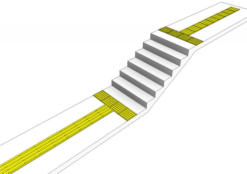
I’m sure anyone who’s ever done a commercial project has needed to show tactile indicators on their documentation.  I noticed some of my clients would simply use a filled region and a detail group.

Tactile Indicators - Warning & Directional

Instead how about using a 3D family so its easier to coordinate.  I based this one on the tiles/pavers/stickers that can be purchased…

As always how should we start…?  By working out what we want the family to do!

  1. We don’t want to have a massive blob of linework in our plans so we’ll definitely need various detail level control.  At coarse we only want to see a blank tile, at medium perhaps we see some of the bumps but scaled up, and at fine we want to see the true representation.
  2. We want to easily be able to place multiple tiles as there could be a lot of these…
  3. We want to be able to manipulate the materials.
  4. We want to be able to change the depth of the Tile.

The rest is all common sense and conforming to the Australia & New Zealand Revit Standards (ANZRS) etc.  So how do we achieve that?

  1. I begin by modelling an extrusion for the base tile and ensuring that its visible at all detail levels.  Then for the bumps these are simply a series of Blends.  In this case we don’t need to worry about arrays because the individual tiles are fixed sizes, so that simplifies things.  We then set these blends to only be visible at fine detail (of course I only drew one and then copied them around).  We now have the coarse and fine detail levels sorted.  For the Medium detail I drew a series of symbolic lines in plan and then set them to only be visible at Medium detail level.
  2. I began by creating the individual tile.  Then I nested these into a “line based” family template.  This way I can simply use 2 pick placement to position the tiles.  I placed one at the start and constrained it using its origin to the start, then did an array to second and constrained the second element with a fixed spacing 300.  I then added a parameter to the number of the array and set a simple formula to control the number of tiles based upon the length.  Sorted!
  3. Too easy, just add a material parameter in the tile family to each of the extrusions/blends, then after nesting the family remember to link through this parameter to one in the host family using the associate family parameter button.
  4. Remember to always use reference planes to control anything parametric, again I just had a top and bottom reference plane, placed a dimension between the 2 and associated a parameter to it.  Then linked that parameter through to the host famliy.

That’s the gist of things.  Download the family here for a more in depth look.  HOPE YOU FIND IT USEFUL!

Posted in Services | Tagged , , , | 6 Comments

Creating a Parametric Step Ladder Family

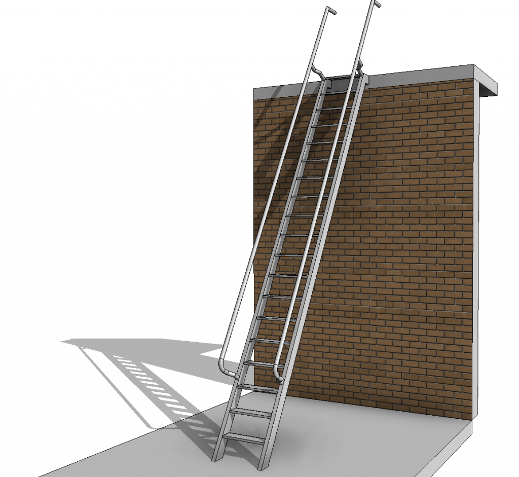
Have you ever needed a step ladder that is designed to conform to AS1657?  Well look no further.  I required one, and figured if I was going to make one, I’d make it unbreakable and make it impossible for the user to set values that don’t meet Australian Standards.

AS1657-1992 Step Ladder

So how did I go about creating this?  As usual I needed to work out exactly what I wanted the family to be able to do.

  1. Make the family easy to place, ie: Level to Level, origin to be the top of ladder so you can place near the wall and when you adjust the values it stays there.
  2. Ensure all the AS1657 minimum and maximum values are adhered to.  That is:
    1. Clear Width between stiles (not less than 450)
    2. Min. & Max. Riser Height (200-250)
    3. Incline Angle (60-70 degrees)
    4. Handrail Clear Width (550-750)
  3. Allow the user to control materials
  4. Allow the user to control Width, Number of Risers, Incline Angle, Tread Thickness, Tread Depth, Offset to wall, Stile Size, Handrail Diameter and Handrail Clear Width
  5. Allow the handrails to extend to guardrails applied at the top level
  6. Show Headroom clearance lines in elevation
  7. Complete Assembly Code & Omniclass values & any other relevant meta-data

To make a level to level based family you need to begin with a template that has two levels in it.  Easy!  Just use the Column or Structural Column template, go to family category & parameters dialog and select the new family category to use.  In my case Specialty Equipment.  I then had to place a reporting parameter between the levels so I can use it in the formulas.

Ensuring values fall within a given range but still allowing the user to specify the values can be tricky in Revit.  We require 2 sets of parameters.  The “desired” values entered by the user, and then the “validated” versions which ensure the desired values fall within the given range.  Its this validated version that is used to drive the actual geometry.

Xrev-Step Ladder Formulas

As you can see there are a series of conditional statements.  That basically say if the value is within this range, then use the desired value, otherwise use the minimum or maximum (depending on what side they on).

The treads are a simple array of a nested family using the array to last option and constraining the first and last element.  The tricky part was the handrails and having them connect to the stiles when the relationship changes.

Anyway I’m feeling extremely generous.  Download the family here.

Leave your comments and hopefully you try out our software as well!

Posted in Services | Tagged , , , | Comments Off on Creating a Parametric Step Ladder Family

Creating the ultimate Louvre Window Family

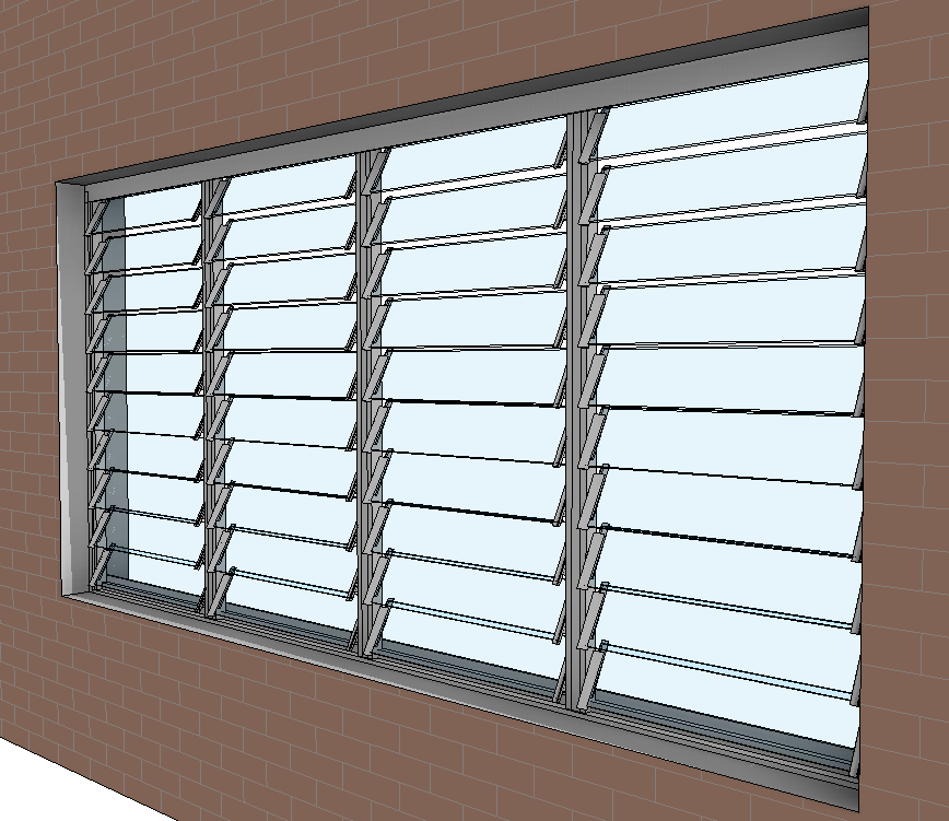
A few months ago Xrev was tasked with creating a series of louvre windows for one of our clients.  We don’t like to do things by halves so we set out to create the best louvre window available.

Our Louvre Window

Before we started we established the requirements:

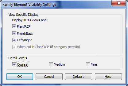
  1. Appropriate detail display at Coarse, Medium & Fine to avoid excessive linework in plans/elevations & section.
  2. The ability for the user to specify any number of bays including 1, from within the same family.
  3. The ability to control the position of the window within the wall (offset in both directions)
  4. The ability to control whether the openness of the louvres
  5. The ability to specify whether the louvres are Glass, Aluminium or Timber
  6. The ability to have non-standard heights and correctly display the infill panel
  7. The ability to change the louvre blade size between 152mm and 102mm
  8. An acceptable file size and performance when making changes
  9. Report to the user when they have selected a non-standard height that is not available from the manufacturer.  EG: Exceeding the maximum height, width, bay width, or setting to an off-standard height that isn’t supported (there are “dead zones” for custom heights).
  10. Control visibility of Weather Seals
  11. Control the Frame Material
  12. Display Structural mullions when the Height exceeds a particular threshold

Did we achieve all of these?  Absolutely.  Lets look at how we addressed each of these items.

  • We simply provided different geometry for coarse that uses a surface pattern for the louvre display.  At medium we we turned off the clips and turn off the coarse display, at fine we show the clips.

  • This one was trickier.  Of course we made use of nesting families.  We modelled up a single louvre blade, nested that into a single louvre bay where they were arrayed and nested that into the host family.  This actually keeps the file size down and gives us a much more control so we can add parameters.  In the host family we had an array for multiple bays, and then a separate “single” element for when the user just selects one bay.  We then simply tell the “array” to be off if the user sets it to 1.  “Multi” = not(Number of Bays < 2).  We then control the array so the family can’t break by adding the following formula. “Actual Bays” = if(Number of Bays < 2, 2, Number of Bays).  Essentially we have two sets of parameters, ones that the user inputs what they “want” and another set that actually drive the geometry where we do some validation to ensure that we give them what they want, but only if its possible.  Of course it gets trickier again as we also have the mullions that we need to control, but I won’t get into that.
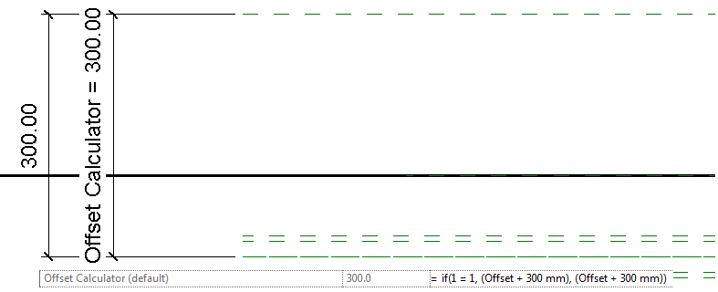
  • As you may know, a parameter that is driven by a dimension cannot flip directions to be a negative value.  As such we again have to use a little workaround to achieve this.  PLEASE NOTE: The rule is a simply “Offset + 300” I’ve just added the conditional statement so the parameter value cannot be edited by the end user.

  • In the Louvre Blade family, I have created all the geometry so it is hosted on a reference line that I have a parameter attached to allow me to change the angle.  Always use reference “lines” to control angles.  These parameters are then “linked” through the various levels of nesting.
  • Louvre material is just simply a material parameter, not tricks there.
  • Having the infill panels work was quite difficult.  To limit file size I didn’t want to create a new family just for those.  As such I added a parametric void the louvre blade family.  I created a switch using an On/Off parameter called Extension Infill, that drives a parameter the moves the void up and down so it intercepts the blade geometry and cuts it only when necessary.  In my Bay family I then had this Infill panel as a new “type”, Tied it to a visibility parameter so its only visible when the overall height requires an infill.  The formulas to determine the infill size get quite long.  “Infill Size” = if((Height – Bottom Spacing – Top Spacing – ((Number Blades – 1) * Spacing)) < 1 mm, 100 mm, (Height – Bottom Spacing – Top Spacing – ((Number Blades – 1) * Spacing) + 26.4 mm))
  • Changing the blade size was just a parameter I built into the extrusion in the louvre blade family. Getting the complicated geometry of the clips to constrain and update was a bit more complicated, as I still needed to control the angle so all this needed to be constrained off the Reference Line.
  • For each nested family I ensured they were full purged, only included the required geometry, and limited the number of nested families by having more parametric types rather than additional families.  Overall file size is 800KB.  Considering how many families it would take to achieve the same amount of options which would each be about 550KB at their leanest, I think this is quite acceptable.
  • For the error message I embedded a symbol family that displays the text I want to see.  This is then connected to a visibility parameter that is driven by a formula that validates whether it needs to display or not.  “Error Message” = or(and(Actual Blade Length > 952 mm, Blade 152, not(Timber Blade)), and(Actual Blade Length > 972 mm, Blade 152, Timber Blade), and(Actual Blade Length > 822 mm, Blade 102, Timber Blade), and(Actual Blade Length > 802 mm, Blade 102, not(Timber Blade)), and(Height > 3018 mm, Blade 152), and(Height > 3048 mm, Blade 102))
  • The next two items are simply material and visibility parameter options.
  • The structural manual is required if the height is greater than 1500mm.  A pretty simple formula.

Anyway, I hope that gives some insight into the lengths we go to to ensure our clients get the best content available and that we always have the end user in mind.  We always populate all the identitiy data parameters, omniclass & uniformat, conform to ANZRS and ultimately make the content robust and easy to use as well as ensuring that it displays appropriately in your documentation.

Posted in Services | Tagged | 2 Comments

Xrev Services

Here at Xrev we don’t just do Revit API tools.  As we have extensive project based experience, we assist companies with Revit Implementation, Training and the absolute best Revit content development available.

Below you can see an image of just some of the great content we have been creating for Design Content, an online Revit Content service.

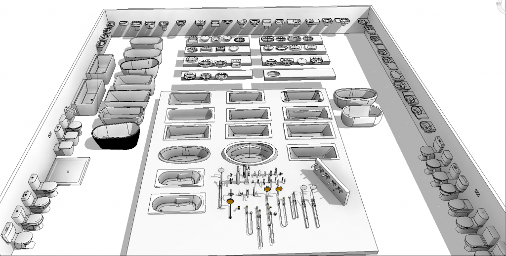
This is just some of the sanitaryware/plumbing equipment I’ve been creating the past month. Of course all are face based, have options to cut the host, correct connectors, taphole options, pedestal/shroud options, material options, symbolic representation in plan/elevation for documentation to keep things looking clear, model elements on their own sub-category so they can be turned off if needed, will make penetrations for wastes if desired.

Let us know if you would use them!

Sanitaryware Revit content created by Xrev

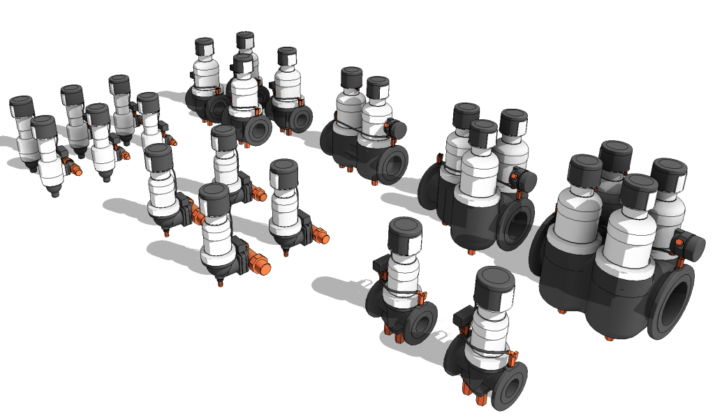
Water Filters Revit Content created by Xrev

Posted in Services | Tagged , , , | 2 Comments

Xrev Transmit – Aconex Integration

With Xrev Transmit now integrating directly with the online collaboration software Aconex, we wanted to clarify some recent queries we’ve had regarding this functionality.

Some users were concerned that they wouldn’t have the chance for the exports and prints to be reviewed prior to being published to Aconex.  When we designed the Aconex integration we were well aware of this requirement.  A number of our customers review each of the PDF’s after the export and digital sign each of them.  Xrev Transmit completely supports this workflow.  The only requirement being that you don’t move the files from where Xrev Transmit exports them to, and you don’t change their names.

Once the drawings are approved for issue, open up your Revit project, choose publish to Aconex and select the files you wish to publish (from the previously exported/printed list of files within Xrev Transmit).  Job done, files are automatically superseded, new files are automatically registered and parameters from Revit are used to pre-populate the Aconex fields.

If you’d like to test on a trial Aconex project prior to using it on a live project, please let us know as we are happy to arrange this with Aconex.

Posted in New Features, News | Tagged , , | Comments Off on Xrev Transmit – Aconex Integration

RTC Australasia 2012 – Great Success

Recently we attended to the RTC Australasia 2012 held at the Novotel, Wollongong, NSW, Australia.  We had two speakers at the event as well as a stand to promote our current products and to provide a sneak peak to the upcoming release.

Chris Price presented a lab on “Finish my Family”, whereby we took 7 broken or inefficient families and went through the process of fixing or optimising them so they were easy to use, looked good in our documentation and didn’t bog down the model.  Everyone was able to follow along and I believe most took some useful tips and tricks away with them to become better family authors.  They also got to take home some highly complex and extremely useful families for free!!

Matt Siebert gave two presentations.  A lab on the Revit API and programming concepts along with a formal talk.  Unfortunately they ended up being scheduled in the wrong order, as the talk was meant to precede the lab.  I believe those in the lab were able to appreciate the complexities with programming and making quality applications, and as a result, Matt only made it through about 50% of the presentation.  As such he will be making the talk available online in a video format so you can play and pause things whilst you follow along.

Our stand was visited by hundreds of Revit users.  Our existing customers were praising us on our current version of Xrev Transmit and advising of the excellent time savings being appreciated by their users.  For many though, it was the first time they have seen Xrev Transmit and were very keen on the benefits to be gained.  For those that saw the all new version we had excellent feedback on our Aconex integration as all users who had experienced Aconex were often frustrated by the data entry steps to fill our all fields per file.  Not when the new Xrev Transmit though as it is able to pre-populate many of the Aconex fields from Revit information and upload both new and supersede existing documents.

Matrix transmittals was another item high on the agenda of our users, are we were glad to be able to say that the new version has made this fairly simple to implement.  So watch this space.

A big thanks to all those that came and visited us and look forward to speaking with you in the future!

Posted in News | Tagged , | 1 Comment