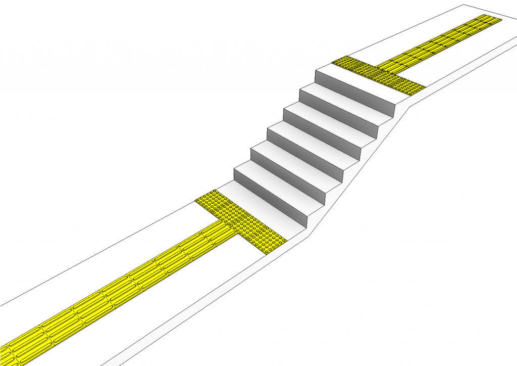
I’m sure anyone who’s ever done a commercial project has needed to show tactile indicators on their documentation. I noticed some of my clients would simply use a filled region and a detail group.
Instead how about using a 3D family so its easier to coordinate. I based this one on the tiles/pavers/stickers that can be purchased…
As always how should we start…? By working out what we want the family to do!
- We don’t want to have a massive blob of linework in our plans so we’ll definitely need various detail level control. At coarse we only want to see a blank tile, at medium perhaps we see some of the bumps but scaled up, and at fine we want to see the true representation.
- We want to easily be able to place multiple tiles as there could be a lot of these…
- We want to be able to manipulate the materials.
- We want to be able to change the depth of the Tile.
The rest is all common sense and conforming to the Australia & New Zealand Revit Standards (ANZRS) etc. So how do we achieve that?
- I begin by modelling an extrusion for the base tile and ensuring that its visible at all detail levels. Then for the bumps these are simply a series of Blends. In this case we don’t need to worry about arrays because the individual tiles are fixed sizes, so that simplifies things. We then set these blends to only be visible at fine detail (of course I only drew one and then copied them around). We now have the coarse and fine detail levels sorted. For the Medium detail I drew a series of symbolic lines in plan and then set them to only be visible at Medium detail level.
- I began by creating the individual tile. Then I nested these into a “line based” family template. This way I can simply use 2 pick placement to position the tiles. I placed one at the start and constrained it using its origin to the start, then did an array to second and constrained the second element with a fixed spacing 300. I then added a parameter to the number of the array and set a simple formula to control the number of tiles based upon the length. Sorted!
- Too easy, just add a material parameter in the tile family to each of the extrusions/blends, then after nesting the family remember to link through this parameter to one in the host family using the associate family parameter button.
- Remember to always use reference planes to control anything parametric, again I just had a top and bottom reference plane, placed a dimension between the 2 and associated a parameter to it. Then linked that parameter through to the host famliy.
That’s the gist of things. Download the family here for a more in depth look. HOPE YOU FIND IT USEFUL!


6 Responses to Creating Tactile Indicators Families (TGSI)